Recently, my Roomba virtual wall broke. Not sure what happened. I did a battery change, and the darn thing will not power up after the new batteries were inserted.

Anyway, while looking online for a new virtual wall to buy, I came across info on people making their own virtual walls. Here is a links dump:
- https://petezah.com/category/development/roomba/
- https://www.thingiverse.com/thing:3104027
- http://blog.batmule.dk/posts/2019/Roomba_Virtual_Wall_part1/
- http://www.robotreviews.com/chat/viewtopic.php?p=65658&mobile=on
- https://misc.ws/2014/02/27/diy-virtual-wall-for-roomba/
- https://misc.ws/2014/08/09/diy-virtual-wall-for-roomba-part-two/
- http://www.enide.net/webcms/index.php?page=virtual-wall-for-roomba
- http://eka.tomeczko.pl/index.php/diy-roomba-virtual-wall
- http://gregthielen.me/blogstuff/2017/06/27/roomba-virtual-wall/
- https://github.com/MKme/Roomba
- http://forkthings.com/2016/11/25/diy-an-irobot-roomba-virtual-wall/
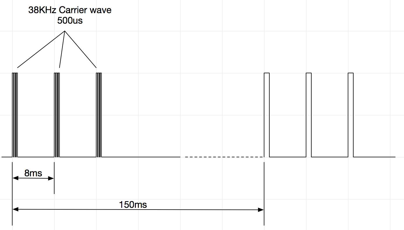
Turns out it is extremely easy to produce the IR signal emitted by the virtual wall. It's basically 0.5ms mark, 7.5ms space, 3 times, followed by 132ms of rest (based on the info given here), over a 38KHz modulation frequency.
I decided to test the idea using a simple ATtiny85-based circuit on the breadboard:

The test program is as follows:
#include <Arduino.h>#include <tiny_IRremote.h>IRsend irsend;
void setup() {
  irsend.enableIROut(38);
}

void loop() {
  for (int i=0; i<3; i++) {
      irsend.mark(500);
      irsend.space(7500);
    }
    delay(132);
}
Being the lazy bum that I am, instead of trying to debug the library, I simply googled around and found another IR remote library called tiny_IRremote. I downloaded the library and changed the include file, and to my amazement, the test circuit worked on first try!
The IR LED that I was using on the breadboard was the one salvaged from the broken virtual wall. I also tested another IR LED that I removed from an old TV remote, as well as a IR LED that I found in the original Arduino kit purchased many years back. They all worked without a problem (at least with the two 500-series Roomba in my possession).
Now that the proof-of-concept works, I am going to build a replacement Roomba virtual wall with the ATtiny85.
Missing the declaration of irsend in this little example
ReplyDeleteFind in tiny_IRremote: https://gist.github.com/SeeJayDee/caa9b5cc29246df44e45b8e7d1b1cdc5
DeleteThanks for your answer. I don't think you got my point; I'm aware that I've to use the lib from this Gist; but I just pointed out that in this POF code the declaration of irsend object is missing:
Delete#include
IRsend irsend; // This was missing
(#include is missing too by the way)
Thanks for this project !
okaayyy ... for some reasons some parts are deleted on comments ... So again, without angle brackets 🤥
Delete#include tiny_IRremote.h // imagine angle brackets ...
IRsend irsend; // <-- This was missing
(#include Arduino.h is missing too by the way; again imagine angle brackets)
Ah, I see! I have fixed up the code. Thanks for pointing out the omissions!
Delete