Thanks to the current corona-virus crisis, the parts I ordered for the filament joiner project were taking forever to arrive. But now that they have finally arrived, I can put them to good use.
These were the parts ordered:
Here is the final circuit diagram:
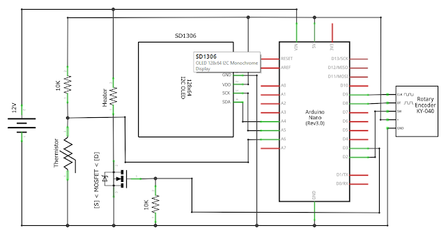
The OLED display is connected to the SDA and SCL pins of the Nano (A4 and A5 respectively), and powered by 5V and GND.
The rotary switch encoder is connected as follows:


The updated code for driving the knob and display is available in heater-with-display.ino in the Github repository.
We now have a fairly compact (about 7cm x 5cm) and independent filament joiner (no need to connect to PC) that is driven solely by a 12V power supply.
Here's how to use it to join printer filaments.
More usage details in my previous post.
These were the parts ordered:
Here is the final circuit diagram:
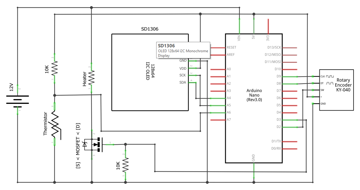
The rotary switch encoder is connected as follows:
- VCC => 5V
- GND = > GND
- CLK => D9
- DT => D8
- SW => D2
My prototype board now looks like this:


The updated code for driving the knob and display is available in heater-with-display.ino in the Github repository.
We now have a fairly compact (about 7cm x 5cm) and independent filament joiner (no need to connect to PC) that is driven solely by a 12V power supply.
Here's how to use it to join printer filaments.
More usage details in my previous post.
If you already utilize a hot end, why would you not actually run the filament through a nozzle instead of grinding the filament against the outside edge of the block?
ReplyDeleteThe hot end was specifically designed to do exactly what you're trying to do - heat filament to a desired temp. Now that you've figured out the hard part, it seems pretty straightforward to add a nozzle, maybe add a chamfer to the "exit" side for easier insertion of the 2nd piece of filament, and tune the temps appropriately.
You don't actually need to add a nozzle. One of the things I have tried initially is to drill a 1.75mm hole through the hotend, align both ends of the filament through the hole, then heat the hotend up to 180c. I quickly learnt that once the filament starts melting, things turn gooey very quickly and the filaments will fall off the hole, even if I quickly turn power off the hotend. Lesson learnt is that once the filament starts melting, it turns into a liquid mess and you lose control over it very quickly.
DeleteHello! How do You calibrate the temp sensor? In room tempeature it shows around 70 degrees celsius?
ReplyDeleteAlso the rotary dimmer is not changing the set value. Have You changed the code lately?
The characteristics of the hotend thermister is defined by this line:
DeleteNTC_Thermistor* thermistor = new NTC_Thermistor(THERMISTOR_PIN, 10000, 100000, 25, 3950);
"10000" is the 10Kohm resister used in the voltage divider. "100000, 25" means the thermister's resistance is 100Kohm at 25c. 3950 is the "b-value" of the thermister. All these parameters can be found in the datasheet of the particular thermister in your hotend.
The rotary encoder code hasn't changed. Anyway, the work is mostly done by the "ClickEncoder" library. I am merely using it to read the encoder value. I suggest you isolate the circuit for the rotary encoder and make it work with the "ClickEnoder" library.
Same here, setpoint stays 0, sometimes 5 for a short moment, no matter how I turn the decoder knob. Seems the encoder software library does not run proper on my arduino nano, could be a timer issue, will try another decoder library. Pushing the knob starts the heater which heats up to 40 dgC. Ambient shows 20 so sensor is ok.
DeleteHi All,
ReplyDeleteActually the encoder works without the +5v input, but in this case you'll lose the click function, probably the capacitance and resistive network around the encoder shoud be carefully calculated.
I solved disconncting the +5 and using an external click button (normally open) in which I feed +5v at one end and A6 and a 1k resistor to ground to the other end. It works.
Hi again,
ReplyDeleteI finally finished the electronics and software; I had to customize for a different LCD screen (nokia 5110 I had laying around) and I somehow changed the thermal control routine since I didn't like the way the pid control worked and I did put some other thermal control just in case; anyway If someone wants the code write to at bagaglia69@gmail.com and I'll send it to you.
That's so cool! Mind giving me a brief overview of what you didn't like about the PID control and how you changed it?
DeleteAlso, I think it would be best if you could just put your code on GitHub so we can all learn from it.
I had to do it on the fly, but here it is
Deletehttps://github.com/AlexBagaglia/filament-joiner
This comment has been removed by the author.
DeleteAlso I'd like to send you the schematic with nokia display so you can publish it on your page, if you agree,
DeleteForgot to tell you, the code is named heater_nokia_display.ino under heater-with-display folder.
DeleteWhat I ddn't like 'bout the pid control?, well it did work, but it was not very stable, I had an histeresys cycle going from +-15 degreec C and sometimes my temps were going much too high almost out of control as if the pid control was very slow to respond, the simple controls I wrote in the code:
1) check if thermistor cable is disconnected (readings can go negative)
2) turn off the mosfet if temp is over settemp
3) put arduino to sleep if there's a thermal runaway
Obviously these aren't good thermal runaway checks as those you find in marlin code, but they do their job. My heater now stays very stable.
Thanks for sharing! I don't recall having such severe overshot, maybe +5c at most, that's why I let the PWM library took care of everything. But if this approach works well for your setup, maybe others will benefit from it as well.
DeleteAs for the schematic diagram, I suggest you create an "images" folder in your GitHub repository and putting the diagram there. Then just link to it in your README.md.
I was new to GitHub when I first started, and learned along the way the "standard" way of doing things. I have always wanted to go back and fix up my old projects as well but kept procrastinating, but I promise I will also fixup my own repository ASAP, and link to your repository.
Happy New Year!
Hello, I was wondering that to power the thermistor, would 0.5A be enough to heat it up? If not, is 8A overkill?
ReplyDeleteThanks in advance :)
Also, for the MOSFET that i'm using, its rated for 1A to -1A and 80V to 5V. Though, for the power supply that i have, there are outputs of 12V 10A and -12V 0.5A (negative 12 volts 500 milliamps). I am confused why it is in negative volts and was wondering if that would still be usable in this project.
DeleteI suspect 0.5A will still do, but it's going to take a much longer time to reach the target temperature. As mentioned in the blog post, I am using a 12V/2A power supply. To be honest, I have never seen a 12V/8A power supply! I would personally be hesitant to use such a large current on such a tiny heater block unless I am really sure about what I am doing!
DeleteNot sure about the -12V/0.5A. Are you sure it's a DC power supply?
Hi there, sorry for the delayed response, I only saw the reply until now.
DeleteBack then, I was using a repurposed PC power supply which had many voltage and current outputs. Now, I have switched to a 12V 2A DC power supply along with a IRFZ44N MOSFET. I'm pretty sure that I've wired up my circuit correctly. However, even after running the autotune code for the PID, I can never seem to get my hotend to heat to the desired temperature. This is running off of a normal Arduino UNO.
Please see my latest reply to Paul Viscovich with regards to debugging.
DeleteI have a question! What's the name of the regulator? Is it L7805?? Is it L7812??
ReplyDeleteI believe I used STP16NF06, rated for 60V/16A. A bit of overkill, I know, but it was what I could get quickly from the local hardware store.
DeleteThank you!
DeleteUnderstanding its been a few years.. I have been attempting to get the PID process to work reliably with your code examples as my starting point. when running autotuned i get values that simply prevent the heater from getting warm.. my issue when adjusting or using your listed values is that i get over shoot on the temps.. also i have been using 12v heaters (things get hotter faster it that)
ReplyDeleteAny suggestions for fine tuning that..
TIA
~Paul
I suggest simply turning on the MOSFET without PID and see if the heater heats up at the expected rate (all the while monitoring the heater temp so that you can power the circuit if it gets too hot). This lets you do check if the circuit is working correctly at supplying power and lets you measure the input voltage at the heater with a multimeter.
DeleteI am quite dumb and am not too sure how to do that. Do I just turn on the heater circuit and on my arduino put the MOSFET gate pin to full so the MOSFET is on?
DeleteHaha! Nobody's dumb, we are all trying to have fun here. Yeah, just set the gate pin to HIGH in your Arduino code and turn the MOSFET on permanently. But make sure you have code reading the thermister (which gives you the temperature of the heater block) and printing it to the console so that you can turn off the power if the temperature gets too high.
DeleteI tested your suggestion and I'm not completely sure whether it is efficient. It took around 4~ minutes to heat from 23 to 44 degrees celcius. My thermistor was reading perfectly initially (without the 12V psu plugged in). I put my hand on it, it would increase slowly towards 26... But then, when I plugged in the 12V power supply, it suddenly read negative degrees celcius. It still read relatively correct values but while the heater block was heating up, it would sometimes jump randomly (from 40 down to 20 down to -1 then back up to 40).
DeleteHowever, when I used a multimeter to read the input voltages, it read that the input voltage for the MOSFET was 3.9V~ and the input voltage to the heater was 2.7V~. Not sure if this is correct. 12V 2A power supply bought from China.
That doesn't sound right. 1) the thermister readout should not be jumping around. Is there a loose connection? Also, make sure your 12V PSU and Arduino share a common ground. 2) When the MOSFET is on (gate pin = 5V), drain to source should measure close to 12V. If it doesn't, check your circuit wiring again. The gate pin acts as a switch. When it is on, the channel from drain to source opens so the full voltage of the 12V PSU should act across the heater block.
DeleteNow the thermistor's value is steady and doesn't jump around (It may have been a loose wire, I'm not too sure). Before, the 12V PSU and Arduino did not have a common ground so I searched how to do it and supposedly it was to connect the source of the MOSFET to GND on the Arduino. I'm not sure how to measure the gate pin of the MOSFET (I measure the voltage of pin 11 to GND to be around 4.95 - pin 11 is the Arduino pin connected to the gate). When measuring the voltage between the drain and source, it is 5.86V. My friend said that the heater takes voltage so it wont be 12V. But someone online said the MOSFET I'm using (IRFZ44N) requires 10V to completely open.
DeleteAlso It took 14 minutes for the heater to get from 23 degrees celcius to 45
DeleteThank you so much for the help :)
Based on the IRFZ44N specs, the gate threshold voltage is 4V, so 4.95V is sufficient to get the MOSFET to fully open. Something is not correct with the voltage between drain to source. Assuming your connection is 12V => drain => heater => source, when the MOSFET is opened and you place the multimeter probes between drain/source, it should read 12V. The "heater takes voltage" argument is only relevant if you are measuring a voltage divider. But now only the heater is sitting between drain and source. If the MOSFET is opened, it is theoretically a closed circuit, so drain = 12V and source = GND. So you should measure 12V between drain and source.
DeleteI personally do not have much experience in the electrical field but from my understanding, current flows in from the drain and then flows out through the source. Though my circuit is not connected in the order that you described, if it were 12V => drain => heater => source, wouldn't the heater be in parallel to the MOSFET? I am not too sure. Similarly, this a datasheet that I am using: https://components101.com/mosfets/irfz44n-datasheet-pinout-features#:~:text=Difference%20between%20IRLZ44N,will%20be%20limited.
DeleteWhen I changed my circuit to the connection you described, the voltage between the drain and the source was still measuring to be 2-3V
My apologies, it should be 12V => heater => drain/source => GND. When +5V is applied to gate, drain/source closes, so the circuit becomes 12V => heater => tiny resistance => GND, so multimeter should measure ~12V across heater.
DeleteYes, that was the way that my circuit was laid out before, 5 volts is going to my gate, but when I measure between drain and source, I am still getting only 5.6 volts. Please see the link from my previous reply. The heater is heating up, just very slowly. Nevertheless, the original problem was that my PID is not very good. No matter the values provided to me from the autotune code, the heater still always takes a long time to heat up (because it takes a long time to heat, I can never tell if it ever gets to my desired temperature).
DeleteFrom the source, it says that the IRLZ44N MOSFET will open fully with 5volts, not the IRFZ44N. If this is the case, I will just order some from aliexpress and see the result.
This comment has been removed by the author.
ReplyDelete